|
|||||||||||||||
FreeRTOS PSoC5 CY8C5588 Demo
|
|||||||||||||||


 |
The demo application has been tested on the following evaluation kits:
- CY8CKIT-001 PSoC® Development Kit
- utilising the CY8CKIT- 010 PSoC® CY8C55 Family Processor Module Kit
The PSoC5 demo includes a schematic design with several peripherals to demonstrate their integration with the RTOS. The included peripherals are the UART, LCD Character Display and two different types of timer implementations.
The demo uses:
- The FreeRTOS GCC and Keil ARM Cortex-M3 ports.
- The PSoC Creator 1.0 beta 5 with its included GNU ARM Toolchain.
- Or the PSoC Creator configured to use the Keil MDK or RVDS ARM Toolchains.
IMPORTANT! Notes on using the PSoC5 ARM Cortex-M3 Demo
Please read all the following points before using this RTOS port.
See also the FAQ My application does not run, what could be wrong?
Source Code Organisation
See the Source Code Organization section of the FreeRTOS site for a description of the downloaded files and information on creating a new project.
PSoC Creator Workspace - GCC
- The PSoC Creator workspace file for the PSoC5 FreeRTOS demo is called FreeRTOS_Demo Workspace.cywrk and is located in the FreeRTOS/Demo/CORTEX_CY8C5588_PSoC_Creator_GCC directory.
PSoC Creator Workspace - Keil
- The PSoC Creator workspace file for the PSoC5 FreeRTOS demo is called FreeRTOS_Demo Workspace.cywrk and is located in the FreeRTOS/Demo/CORTEX_CY8C5588_PSoC_Creator_Keil directory.
PSoC Creator Workspace - RVDS
- The PSoC Creator workspace file for the PSoC5 FreeRTOS demo is called FreeRTOS_Demo Workspace.cywrk and is located in the FreeRTOS/Demo/CORTEX_CY8C5588_PSoC_Creator_RVDS directory.
The Demo Application
PSoC5 Demo application setup
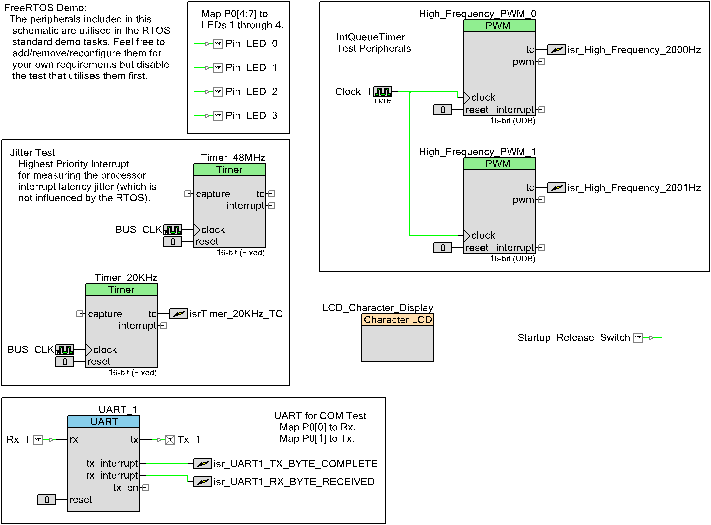
The PSoC5 contains reconfigurable hardware. The Schematic Design for the components required by the demo is shown here. The design includes: four digital outputs, one digital input, a UART driver and four separate timers, two implemented as PWMs and two as Timers. The Schematic Design requires the outputs and inputs to be mapped to physical pins on the board. These pins can be configured in the Design-wide-resource but the defaults are documented below.
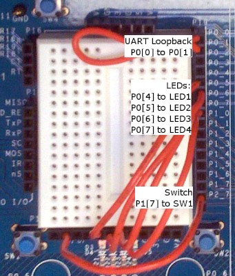
To enable the LEDs and UART COM tests, there are several connections that need to be made on the board.
- P0[0] connects to Rx for UART input or P0[1] for loopback.
- P0[1] connects to Tx for UART output or P0[0] for loopback.
- P0[4] connects to LED1.
- P0[5] connects to LED2.
- P0[6] connects to LED3.
- P0[7] connects to LED4.
- P1[7] connects to SW1.
The demo application also utilises the LCD Character Display which consumes pins P2[0:6]. No additional set-up is required.
The CY8C5588 is programmed and debugged using the MiniProg3 Programmer/Debugger. You will be prompted to install various USB drivers the first time a USB connection is made between the evaluation board and a PC. The required USB drivers are installed as part of the PSoC Programmer which may be prompted during the PSoC Creator installation.
Building and executing the demo application
All three demo applications utilise the PSoC Creator IDE but are configured to use different toolchains to compile and link.
- Using the included GCC toolchain
- Open the FreeRTOS/Demo/CORTEX_CY8C5588_PSoC_Creator_GCC/FreeRTOS_Demo Workspace.cywrk workspace file from within the PSoC Creator IDE.
- Select 'Clean and Build FreeRTOS_Demo' from the IDE 'Build' menu. The project should build with no errors or warnings.
- Follow the Programming and Debugging instructions.
- Using the Keil ARM toolchain
- Open the FreeRTOS/Demo/CORTEX_CY8C5588_PSoC_Creator_Keil/FreeRTOS_Demo Workspace.cywrk workspace file from within the PSoC Creator IDE.
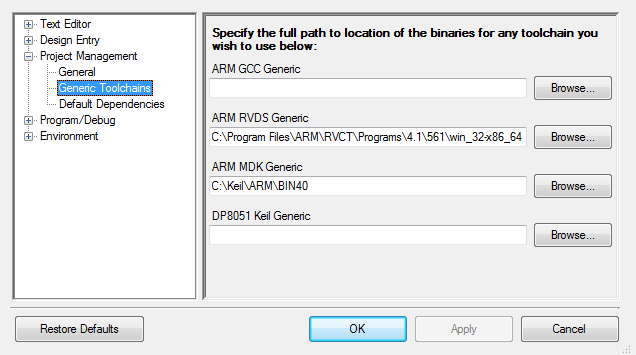
- Select 'Options' from the IDE 'Tools' menu. In the 'Options' dialog, expand 'Project Management' and select 'Generic Toolchains'.
- For the 'ARM MDK Generic' click the 'Browse' button and navigate to the directory in the Keil installation that contains the 'arm[ar|asm|cc|link].exe' tools. For example, C:\Keil\ARM\BIN40. Click 'OK' to accept.
- In the main IDE window, right-click on blank toolbar area to bring up a context menu and select 'Build Configuration / Toolchain'. Ensure that 'ARM MDK Generic' is selected from the second drop-down list box in the 'Build Configuration / Toolchain' toolbar.
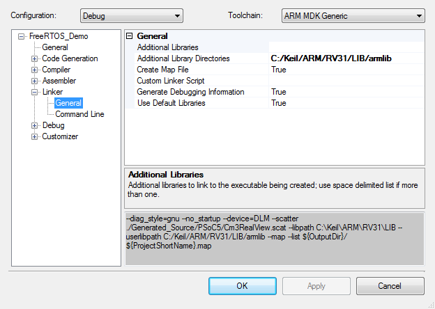
- Select 'Build Settings' from the IDE 'Project' menu. Expand 'Linker' and select 'General' within the 'Build Settings' dialog.
- Modify the 'Additional Library Directories' to include the path to the MDK 'armlib' directory. For example, C:/Keil/ARM/RV31/LIB/armlib. Click 'OK' to accept.
- Select 'Clean and Build FreeRTOS_Demo' from the IDE 'Build' menu. The project should build with no errors or warnings.
- Follow the Programming and Debugging instructions.
- Using the RVDS ARM toolchain
- Open the FreeRTOS/Demo/CORTEX_CY8C5588_PSoC_Creator_RVDS/FreeRTOS_Demo Workspace.cywrk workspace file from within the PSoC Creator IDE.
- Select 'Options' from the IDE 'Tools' menu. In the 'Options' dialog, expand 'Project Management' and select 'Generic Toolchains'.
- For the 'ARM RVDS Generic' click the 'Browse' button and navigate to the directory in the RVDS installation that contains the 'arm[ar|asm|cc|link].exe' tools. For example, C:\Program Files\ARM\RVCT\Programs\4.1\561\win_32-x86_64. Click OK to accept.
- In the main IDE window, right-click on blank toolbar area to bring up a context menu and select 'Build Configuration / Toolchain'. Ensure that 'ARM MDK Generic' is selected from the second drop-down list box in the 'Build Configuration / Toolchain' toolbar.
- Select 'Clean and Build FreeRTOS_Demo' from the IDE 'Build' menu. The project should build with no errors or warnings.
- Follow the Programming and Debugging instructions.
- Programming and Debugging
- Select 'Select Debug Target...' from the IDE 'Debug' menu. In the dialog, select the MiniProg3 with matching serial number. Click 'Port Acquire', select the PSoC5 device and click the 'Connect' button followed by closing the dialog.
- Select 'Execute Code' from the IDE 'Debug' menu. The demo application will be programmed into the flash memory and the debugger will halt at main().
- Select 'Continue' from the IDE 'Debug' menu.
- Alternatively, to Program the application into the flash, select 'Program' from the IDE 'Debug' menu. The demo application will be programmed into the flash memory, the device will be reset and start executing the application.
- If necessary, press the SW1 switch on the board to allow the demo application to proceed.
Functionality
The demo application creates 52 persistent tasks, and periodically dynamically creates and destroys another 2. These tasks consist predominantly of the standard demo application tasks (see the demo application section for details of the individual tasks).
The following tasks and tests are created in addition to the standard demo tasks:
- High priority interrupt test
A high frequency periodic interrupt is generated using a free running timer to demonstrate the use of the configKERNEL_INTERRUPT_PRIORITY configuration constant. The interrupt service routine measures the number of processor clocks that occur between each interrupt - and in so doing measures the jitter in the interrupt timing. The maximum measured jitter time is latched in the usMaxJitter variable, and displayed on the LCD display by the 'Check' task as described below. The fast interrupt is configured and handled in the timertest.c source file. This demonstrates how the RTOS kernel can be configured so as to have no impact on higher priority interrupt processing.
- Check Task
This only executes every five seconds. Its main function is to check that all the standard demo tasks are still operational. Should any unexpected behaviour within a demo task be discovered the Check Task' function will write an error code to the LCD. If all the demo tasks are executing with their expected behaviour then the check task writes Pass with the number of iterations it has completed and the max jitter time to the LCD, as described above.
- Interrupt Queue test
The PWM peripherals generate interrupts at 2000Hz and 2001Hz. These interrupts are used as triggers to manipulate queues which generate context switching between tasks that are waiting on those queues. The Interrupt frequency is much higher than the System Tick pre-emption meaning that the interrupts cause much more frequent context switching between a subset of tasks.
When executing, the demo application will behave as follows:
- The 'Check' Task will write "Pass" with the number of completed check iterations and the jitter time in nanoseconds to the display every 5 seconds.
- If a standard demo task fails, then the 'Check' task will print "Fail" with the iteration when the failure was detected and the jitter time in nanoseconds to the display every 5 seconds.
- LEDs 1, 2 and 3 are controlled by the standard demo 'flash' tasks. Each will toggle at a fixed but different frequency.
- LED 4 is controlled by the standard demo COM test Tx task. It will toggle each time a character is transmitted. The UART is configured for loopback mode, so each transmitted character will be received by the COM test Rx task.
RTOS Configuration and Usage Details
RTOS port specific configuration
Configuration items specific to these demos are contained in FreeRTOS/Demo/CORTEX_CY8C5588_PSoC_Creator_nnn/FreeRTOSConfig.h (where nnn is the compiler being used). The constants defined in this file can be edited to suit your application. In particular -
- configTICK_RATE_HZ
This sets the frequency of the RTOS tick. The supplied value of 1000Hz is useful for testing the RTOS kernel functionality but is faster than most applications require. Lowering this value will improve efficiency.
- configKERNEL_INTERRUPT_PRIORITY and configMAX_SYSCALL_INTERRUPT_PRIORITY
See the RTOS kernel configuration documentation for full information on these configuration constants.
Attention please!: Remember that ARM Cortex-M3 cores use numerically low priority numbers to represent HIGH priority interrupts, which can seem counter-intuitive and is easy to forget! If you wish to assign an interrupt a low priority do NOT assign it a priority of 0 (or other low numeric value) as this can result in the interrupt actually having the highest priority in the system - and therefore potentially make your system crash if this priority is above configMAX_SYSCALL_INTERRUPT_PRIORITY.
The lowest priority on a ARM Cortex-M3 core is in fact 255 - however different ARM Cortex-M3 vendors implement a different number of priority bits and supply library functions that expect priorities to be specified in different ways. Use the supplied examples as a reference.
The Cypress Design Wide Resource can be used to configure the priority of the interrupts generated by each of the peripherals. If the application provides its own implementation of an interrupt service routine, which accesses the Kernel API, ensure that the priority is equal to or numerically greater than the configMAX_SYSCALL_INTERRUPT_PRIORITY so it in effect has a lower actual priority.
To install a customised interrupt service routine, call the Peripheral_StartEx(vCustomISR) function (where 'Peripheral' is the name of the peripheral to which the ISR relates) passing the interrupt service routine function which had its prototype declared as CY_ISR_PROTO(vCustomISR) and the function declared with CY_ISR(vCustomISR). See the function vInitialiseTimerForIntQTests() in IntQueueTimer.c for an example. In this function the ISR is installed using a call to isr_High_Frequency_2001Hz_StartEx().
Each port #defines 'BaseType_t' to equal the most efficient data type for that processor. This port defines BaseType_t to be of type long.
Note that vPortEndScheduler() has not been implemented.
Interrupt service routines
In the demo application the vector table is copied into the RAM.
Unlike most ports, interrupt service routines that cause a context switch have no special requirements and can be written as per the compiler documentation.
The macro portEND_SWITCHING_ISR() can be used to request a context switch from within an ISR. The ISR called vUartRxISR() in serial.c demonstrates portEND_SWITCHING_ISR() being used.
Note that portEND_SWITCHING_ISR() will leave interrupts enabled.
Note also the information provided in the "RTOS port specific configuration" section above regarding the installation of custom interrupt service routines.
Switching between the pre-emptive and co-operative RTOS kernels
Set the definition configUSE_PREEMPTION within FreeRTOS/Demo/CORTEX_CY8C5588_PSoC_Creator_nnn/FreeRTOSConfig.h (where nnn is the compiler being used) to 1 to use pre-emption or 0 to use co-operative.
Compiler options
As with all the ports, it is essential that the correct compiler options are used. The best way to ensure this is to base your application on the provided demo application files.
Memory allocation
Source/Portable/MemMang/heap_2.c is included in the ARM Cortex-M3 demo application project to provide the memory allocation required by the RTOS kernel. Please refer to the Memory Management section of the API documentation for full information.
The Design-wide-resource, FreeRTOS_Demo.cydwr, contains configuration options for generating a linker script. Select the 'System' tab and expand 'Configuration' to configure the 'Heap Size' when using Heap 3, Source/Portable/MemMang/heap_3.c, as part of your project.
NXP tweet showing LPC5500 (ARMv8-M Cortex-M33) running FreeRTOS.
Meet Richard Barry and learn about running FreeRTOS on RISC-V at FOSDEM 2019
Version 10.1.1 of the FreeRTOS kernel is available for immediate download. MIT licensed.
View a recording of the "OTA Update Security and Reliability" webinar, presented by TI and AWS.
FreeRTOS and other embedded software careers at AWS.

![]()


![]()