|
|||||||||||||||
Atmel AT91SAM7S64 (AT91 ARM7) Port
|
|||||||||||||||


|
This Atmel SAM7 ARM7 port was developed on an AT91SAM7S-EK development/prototyping board from the AT91SAM7S64-IAR evaluation kit (instructions are provided should you wish to use an alternative development board). Two FreeRTOS embedded web server demos also exist for the SAM7 series of microcontrollers.
The AT91SAM7S64 is a peripheral rich (including a USB 2.0 device), low pin count ARM7TDMI based flash microcontroller. The evaluation kit came with a non time limited evaluation version of the IAR Embedded Workbench development tools for ARM (32KB limited), a J-Link USB JTAG debugger interface and a USB cable through which the development hardware can be powered. Everything required to start development.
The development tools include a compiler, assembler and linker tool chain along with an IDE and a limited functionality simulator.
A nice feature of this system is the library support provided by Atmel for the majority of the on board peripherals. This greatly speeds development and has so far proved reliable.
This demo includes a USB HID class example driver (as described below). The SAM7X lwIP embedded web server demo includes a USB CDC class example driver.
Note: If this project fails to build then it is likely the version of IAR Embedded Workbench being used is too old. If this is the case, then it is also likely that the project file has been (silently) corrupted and will need to be restored to its original state before it can be built even with an updated IAR version.
IMPORTANT! Notes on using the Atmel ARM7 RTOS port
Please read all the following points before using this RTOS port.See also the FAQ My application does not run, what could be wrong?
Source Code Organisation
The FreeRTOS download contains the source code for all the FreeRTOS ports. See the Source Code Organization section for a description of the downloaded files and information on creating a new project.A THUMB mode sample project is included for the IAR ARM7 port. The workspace rtosdemo.eww can be found in the Demo/ARM7_AtmelSAM7S64_IAR directory and should be opened from within the Embedded Workbench IDE.
The Demo/ARM7_AtmelSAM7S64_IAR/SrcIAR and the Demo/ARM7_AtmelSAM7S64_IAR/resource directories contain support files for the Atmel libraries and build environment.
The Demo/ARM7_AtmelSAM7S64_IAR/serial and Demo/ARM7_AtmelSAM7S64_IAR/USB directories contain sample interrupt driven serial port and USB drivers respectively.
The Demo Application
The FreeRTOS source code download includes a fully preemptive multitasking demo application for the SAM7 RTOS port.Demo application hardware setup
The demo application includes tasks that send and receive characters over the serial port. The characters sent by one task need to be received by another - if any character is missed or received out of sequence an error condition is flagged. A loopback connector is required on the serial port for this mechanism to operate (simply connect pins 2 and 3 together on the serial port connector).The demo application uses the LEDs built into the prototyping board so no other hardware setup is required.
Building the demo application for debug
Two project configurations are provided. "Flash Debug" does not use any optimisation and can be used with the J-Link JTAG debug interface. "Flash Bin" has full optimisation.
Simply open the rtosdemo workspace file from within the IAR Embedded Workbench IDE, ensure flash debug is the selected
configuration (see picture below), then select 'Built Target' from the IDE 'Project' menu.
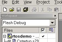
Selecting the flash debug configuration
Running the demo application
The IAR port cannot be executed using the IAR simulator so must be executed on the target hardware.
- Ensure the J-Link JTAG debug interface is connected and that the prototype board is power up.
- Select 'Debug' from the IDE 'Project' menu.
- The embedded microcontroller Flash memory will automatically get programmed with the demo application, and the debugger will break at the reset vector (address 0). Select 'Go' from the IDE 'Debug' menu to start the application executing.
Functionality
The demo application creates 26 tasks - consisting predominantly of the standard demo application tasks (see the demo application section for details of the individual tasks). In addition there is a USB demo task.When executing correctly the demo application will behave as follows:
- The prototyping board will identify itself to a USB host as a simple 3 axis joystick and then periodically transmit updated coordinate values. This is described fully in by the next sub section.
- LEDs PA.0, PA.1 and PA.2 are under control of the 'flash' tasks. Each will flash at a constant frequency, with LED PA.0 being the fastest and LED PA.2 being the slowest.
- Not all the tasks update an LED so have no visible indication that they are operating correctly.
Therefore a 'Check' task is created whose job it is to ensure that no errors have been detected in any of the other tasks.
LED PA.3 is under control of the 'Check' task. Every three seconds the 'Check' task examines all the tasks in the system to ensure they are executing without error. It then toggles LED PA.3. If LED PA.3 is toggling every three seconds then no errors have ever been detected. The toggle rate increasing to 500ms indicates that the 'Check' task has discovered at least one error. This mechanism can be checked by removing the loopback connector from the serial port (described above), and in doing so deliberately generating an error.
USB Functionality
[this has only be tested from a Win2K host]
The demo USB task emulates a simple three axis joystick. To check the USB functionality:
-
Connecting a USB cable between the prototyping board and a USB host will commence the USB enumeration process and
cause the following "found new hardware" dialogue to be displayed.
The "found new hardware" dialogue
A second dialogue may also be observed if this is the first "human interface device" to be installed on your PC.If you are powering the prototyping board from the USB port the enumeration process will start immediately the demo application starts to execute.
-
If prompted to do so, reset your PC.
If you are executing the FreeRTOS demo application from the debugger then remove the USB cable prior to resetting your PC. Now the microcontroller flash has been programmed you can remove the JTAG debugger interface also - the program will then start to execute as soon as you reconnect the USB cable.
-
With the USB cable connected, open the "Gaming Options" (sometimes listed as "Game Controllers") folder from the Windows Control Panel.
This will open the "Gaming Options" dialogue, where the FreeRTOS Joystick should be listed, with the status shown as "OK".
Selecting the "Gaming Options" folder
The FreeRTOS Joystick listed under Gaming Options -
Select the FreeRTOS Joystick from the list (the picture above shows this as the only controller in the list).
Click properties to see the data being transmitted from the USB demo task. The X and Y axis should move in a square,
and the Z axis just keep moving from maximum to minimum.
Data display for the three axis -
The FreeRTOS Joystick device can be uninstalled from the Windows device manager, where it will be listed as a
"HID compliant games controller" under "Human interface devices".
Uninstalling the FreeRTOS Joystick
Configuration and Usage Details
RTOS port specific configuration
Configuration items specific to this port are contained in Demo/ARM7_AT91SAM7S64_IAR/FreeRTOSConfig.h. The constants defined in this file can be edited to suit your application. In particular - the definition configTICK_RATE_HZ is used to set the frequency of the RTOS tick. The supplied value of 1000Hz is useful for testing the RTOS kernel functionality but is faster than most applications require. Lowering this value will improve efficiency.Each port #defines 'BaseType_t' to equal the most efficient data type for that processor. This port defines BaseType_t to be of type long.
Note that vPortEndScheduler() has not been implemented.
Interrupt service routines
An interrupt service routine that does not cause a context switch has no special requirements and can be written as per the normal IAR syntax. For example:
    static __arm __irq void vAnISR( void )
    {
        /* ISR C code goes here. */

        /* End the interrupt in the AIC. */
        AT91C_BASE_AIC->AIC_EOICR = 0;
    }
Often you will require an interrupt service routine to cause a context switch. For example a serial port character being received may wake a high priority task that was blocked waiting for the character. If the ISR interrupted a lower priority task then it should return immediately to the woken task. Limitations in the IAR inline assembler necessitate such interrupt service routines include an assembly file wrapper.
An example of an ISR with context switching capabilities
The main body of the ISR can be written in C within any source file as per the following template. This is just a normal ARM mode function that includes a call to portEND_SWITCHING_ISR() at its end.
    /* For simplicity the C function should operate in ARM mode.
       Note that the __irq modifier is NOT used. */

    __arm void vASwitchingISR( void )
    {
        char cContextSwitchRequired;

        /* Write the ISR body here as per normal.

        A boolean is used to say whether a context switch is required.
        In this example assume we posted onto a queue and this caused a
        task to be woken. */

        cContextSwitchRequired = pdTRUE;

        /* Immediately before the end of the ISR call the
        portEND_SWITCHING_ISR() macro. */

        portEND_SWITCHING_ISR( ( cContextSwitchRequired ) );

        /* End the interrupt in the AIC. */
        AT91C_BASE_AIC->AIC_EOICR = 0;
    }
See the function vSerialISR() defined in Demo/ARM7_AtemlSAM7S64_IAR/serial/serial.c for a complete example.
The entry point for the ISR has to be written in an assembly file. This just places a call to the C function between
calls to the portSAVE_CONTEXT() and portRESTORE_CONTEXT() macros respectively as per the following template:
        EXTERN vASwitchingISR
        PUBLIC vASwitchingISREntry

    /* This header defines the save/restore macros. */
    #include "ISR_Support.h"

    vASwitchingISREntry:

        portSAVE_CONTEXT      ; Call portSAVE_CONTEXT macro first
        bl  vASwitchingISR    ; Then call the function written in the C file.
        portRESTORE_CONTEXT   ; Call portRESTORE_CONTEXT last.

        END
See the file Demo/ARM7_AtemlSAM7S64_IAR/serial/serialIAR.S79 for a complete example.
To use a prototyping board other than the AT91SAM7S-EK
The file Demo/ARM7_AT91SAM7S64_IAR/FreeRTOSConfig.h includes the 'board.h' header file. This defines a few constants relevant only to the Atmel evaluation board and should be replaced or updated when used with any other target hardware.To use a part other than an AT91SAM7S64
The AT91SAM7S128 and AT91SAM7S256 are larger memory versions of the AT91SAM7S64 and should provide direct substitutions. The smaller pin count AT91SAM7S32 is also compatible but does not include a USB device peripheral.The SAM7 family uses a standard ARM7 core so the main real time kernel components are portable across all ARM7 devices - but the peripheral setup and memory requirements will require consideration. Items to consider:
- prvSetupTimerInterrupt() in Source/portable/IAR/AtmelSAM7S64/port.c configures the ATM91SAM7S64 PIT to generate the RTOS tick.
- Port, memory access and system clock configuration is performed by prvSetupHardware() within Demo/ARM7_AtmelSAM7S64_IAR/main.c.
- The interrupt service routine setup and management assume the existence of the advanced interrupt controller.
- The serial port drivers.
- Register location definitions are provided the file board.h (plus others) which is included at the top of Demo/ARM7_AT91SAM7S64_IAR/FreeRTOSConfig.h.
- Startup code, memory map and vector table setup is contained within Demo/ARM7_AtemlSAM7S64_IAR/SrcIAR/CStartup.s79.
- RAM size - see Memory Allocation below.
Switching between the pre-emptive and co-operative RTOS kernels
Set the definition configUSE_PREEMPTION within Demo/ARM7_AT91SAM7S64_IAR/FreeRTOSConfig.h to 1 to use pre-emption or 0 to use co-operative.Compiler options
As with all the ports, it is essential that the correct compiler options are used. The best way to ensure this is to base your application on the provided demo application project file - as described in the Source Organization section.Execution Context
The RTOS scheduler executes in supervisor mode, tasks execute in system mode.NOTE! : The processor MUST be in supervisor mode when the RTOS scheduler is started (vTaskStartScheduler is called). The demo applications included in the FreeRTOS download switch to supervisor mode prior to main being called. If you are not using one of these demo application projects then ensure Supervisor mode is entered before calling vTaskStartScheduler().
Interrupt service routines always run in ARM mode. All other code executes in THUMB mode.
Demo/ARM7_AtemlSAM7S64_IAR/SrcIAR/CStartup.s79 does not configure stacks for all operation modes.
SWI instructions are used by the real time kernel and can therefore not be used by the application code.
'System Interrupts' can be generated from more than one source. Currently all system interrupts are assumed to originate from the PIT (periodic interval timer). The use of any other system interrupts will necessitate some wrapper code to ascertain the interrupts origin.
Memory allocation
Source/Portable/MemMang/heap_1.c is included in the ARM7 demo application project to provide the memory allocation required by the real time kernel. Please refer to the Memory Management section of the API documentation for full information.Serial port driver
It should also be noted that the serial drivers are written to test some of the real time kernel features - and they are not intended to represent an optimised solution. In particular they do not make use of the Peripheral Data Controller.
USB driver
The USB driver is provided for demonstration only. Although functional, it is a minimal implementation that is not fully USB device compliant.
IAR compiler notes
The FreeRTOS source code has to be built with lots of different compilers. The IAR compiler has particularly strong (pedantic) source checking and generates several warnings when compiling the FreeRTOS source code.
Unfortunately these warning cannot be fixed by modifying the source code as they predominantly relate to benign code that was
added in order to fix warnings generated by other compilers (mainly relating to type casting).
Some warnings have therefore been disabled in the project file.
NXP tweet showing LPC5500 (ARMv8-M Cortex-M33) running FreeRTOS.
Meet Richard Barry and learn about running FreeRTOS on RISC-V at FOSDEM 2019
Version 10.1.1 of the FreeRTOS kernel is available for immediate download. MIT licensed.
View a recording of the "OTA Update Security and Reliability" webinar, presented by TI and AWS.
FreeRTOS and other embedded software careers at AWS.

![]()


![]()